Design drawings
Design drawings are used to develop and communicate ideas about a developing design:
In the early stages of the project phase (during the design and tender process) they might simply demonstrate to the client the ability of a particular design team to undertake the design. They may then be used to:
- Develop and communicating the brief.
- Investigate potential sites and assess options.
- Develop the approved idea into a coherent and co-ordinated design.
- Communicate the developed design to other parties, such as the local planning authority, the building control body, contractors and suppliers.
- Record the completed construction.
- Record ongoing changes to the completed construction.
Some of these drawings are not traditionally considered to be ‘design’ drawings, as either the design proper has not begun, or the design has effectively already been completed. However, almost all of them will include some element of an investigation into, or development of the design, or they would serve no purpose.
Very broadly, design drawings are categorised as:
- Feasibility studies.
- Options appraisals.
- Concept drawings. Some designers will differentiate between 'conceptual design' and 'schematic design'. In this case, the 'concept' is the initial design idea, whereas the 'scheme' develops the concept, taking on board more functional and practical considerations.
- Detailed design drawings (or developed design drawings).
- Technical drawings.
- Tender drawings.
- Shop drawings, installation drawings and construction drawings.
Design drawings will develop in detail from block and massing drawings and sketches to very detailed technical drawings describing every component in a way that will enable them to be constructed and operated.
When developing design drawings, it is important to consider what their purpose is, what information they are intended to convey and who they are intended to convey it to. This will determine their format, content, size, scale, and so on. For example, design drawings prepared for an inexperienced client may need to be very clear and to present only necessary information, at a scale and format that the client can easily view and share. Drawings for suppliers, on the other hand, may need to be very detailed and in a format that can be used for fabrication.
Design drawings may be prepared by a number of different practitioners, such as; architects, technicians and technologists, structural engineers, civil engineers, building services engineers, interior designers, landscape designers, contractors, subcontractors, suppliers, and so on. Some elements may first be designed by one individual or organisation and then taken on and developed by another.
It is important therefore that they are carefully integrated and co-ordinated to ensure that all elements are designed to an appropriate level of detail at the right time, and that designs prepared by different members of the project team create a single, unified set of information that can be constructed without clashes between components.
Typically, a lead designer will be appointed whose role includes integrating different aspects of the design and their interfaces into the overall design. Amongst other things, this may involve:
- Ensuring collaborative practices are adopted.
- Coordinating quality control systems.
- Adopting standard methods and procedures.
- Coordinating the preparation and issue of production information to contractors and suppliers.
- Reviewing designs prepared by contractors and suppliers.
Different parts of the design team may also have design managers with an enabling and co-ordinating role.
The preparation of design drawings has been revolutionised by the emergence first of computer aided design (CAD) and then building information modelling (BIM). BIM allows the whole project team to collaborate on the development of a single integrated information model (although at level 2, this model is a ‘federated’ combination of separate models). However, the principle is the same as for traditional design in that the model will begin by communicating design intent, and will develop to become a virtual construction model.
In the early stages, it is likely to include massing diagrams or 2D symbols to represent generic elements of the design, with some critical elements developed in more detail. As the design progresses, the model will develop and the level of detail will increase, including, first, objects based on generic representations, and then specific objects with specifications and method statements attached along with information about space allocation for operation, access, maintenance, installation, replacement, and so on. Ultimately, it will contain all the information necessary to allow the objects in the model to be manufactured, installed or constructed and then operated.
Where BIM differs from traditional drawings is that a great deal of effort is put into defining the level of detail that is required for each element of the design at each stage of its development.
See also Types of drawings for building design for a description of different drawing formats and projections.
[edit] Related articles on Designing Buildings
- As-built drawings and record drawings.
- Assembly drawing.
- Building information modelling.
- Construction drawing.
- Detail drawing.
- Component drawing.
- Concept drawing.
- Design information.
- Design intent.
- Drawings.
- Elevations.
- General arrangement drawing.
- Information manager.
- Installation drawings.
- Lead designer.
- Level of Development LOD.
- North American Paper Sizes.
- Notation and units on drawings and documents.
- Orthogonal plan.
- Paper sizes.
- PAS 1192-2.
- Prefabrication.
- Production information.
- Project information.
- Projections.
- Residential design and 3D rendering.
- Scale drawing.
- Section drawing.
- Shop drawings.
- Space planning.
- Suppliers.
- Symbols on architectural drawings.
- Technical drawing.
- Technical drawing pen sizes.
- Types of drawing.
- Working drawings.
Featured articles and news
The restoration of the novelist’s birthplace in Eastwood.
PAC report on the Remediation of Dangerous Cladding
Recommendations on workforce, transparency, support, insurance, funding, fraud and mismanagement.
New towns, expanded settlements and housing delivery
Modular inquiry asks if new towns and expanded settlements are an effective means of delivering housing.
Building Engineering Business Survey Q1 2025
Survey shows growth remains flat as skill shortages and volatile pricing persist.
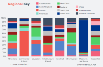
Construction contract awards remain buoyant
Infrastructure up but residential struggles.
Home builders call for suspension of Building Safety Levy
HBF with over 100 home builders write to the Chancellor.
CIOB Apprentice of the Year 2024/2025
CIOB names James Monk a quantity surveyor from Cambridge as the winner.
Warm Homes Plan and existing energy bill support policies
Breaking down what existing policies are and what they do.
Treasury responds to sector submission on Warm Homes
Trade associations call on Government to make good on manifesto pledge for the upgrading of 5 million homes.
A tour through Robotic Installation Systems for Elevators, Innovation Labs, MetaCore and PORT tech.
A dynamic brand built for impact stitched into BSRIA’s building fabric.
BS 9991:2024 and the recently published CLC advisory note
Fire safety in the design, management and use of residential buildings. Code of practice.


